The Dryad
The Dryad is a modular timber gridshell which through its unique form creates an efficient roof system & has intelligent interactions with sunlight
In Fall 2020, I took a class called Structural Design Project I, and as a semester long project students were tasked with creating a long spanning roof structure that would enclose an existing courtyard at M.I.T located between buildings 1 & 5. The roof was judged on the following metrics.
Weight
Embodied Carbon
Structural Feasibility
Feasibility of Construction
Aesthetics
My team and I decided to create a modular timber gridshell called, The Dryad, for the mythological dryad, which is a nymph in Greek stories that inhabits forests or trees, specifically oak trees. Our design goals were to have the smallest embodied carbon footprint, lightest dead weight, and create a design that embraced the location of the structure at MIT and in the greater Boston/Massachusetts area.
Project Members
Nebyu Haile
Claire Holley
Sabrina Madera
Programs + Tools used
Rhinoceros 3D
Grasshopper
MATLAB
Karamba - Structural Analysis Plugin for Grasshopper
Problem Statement
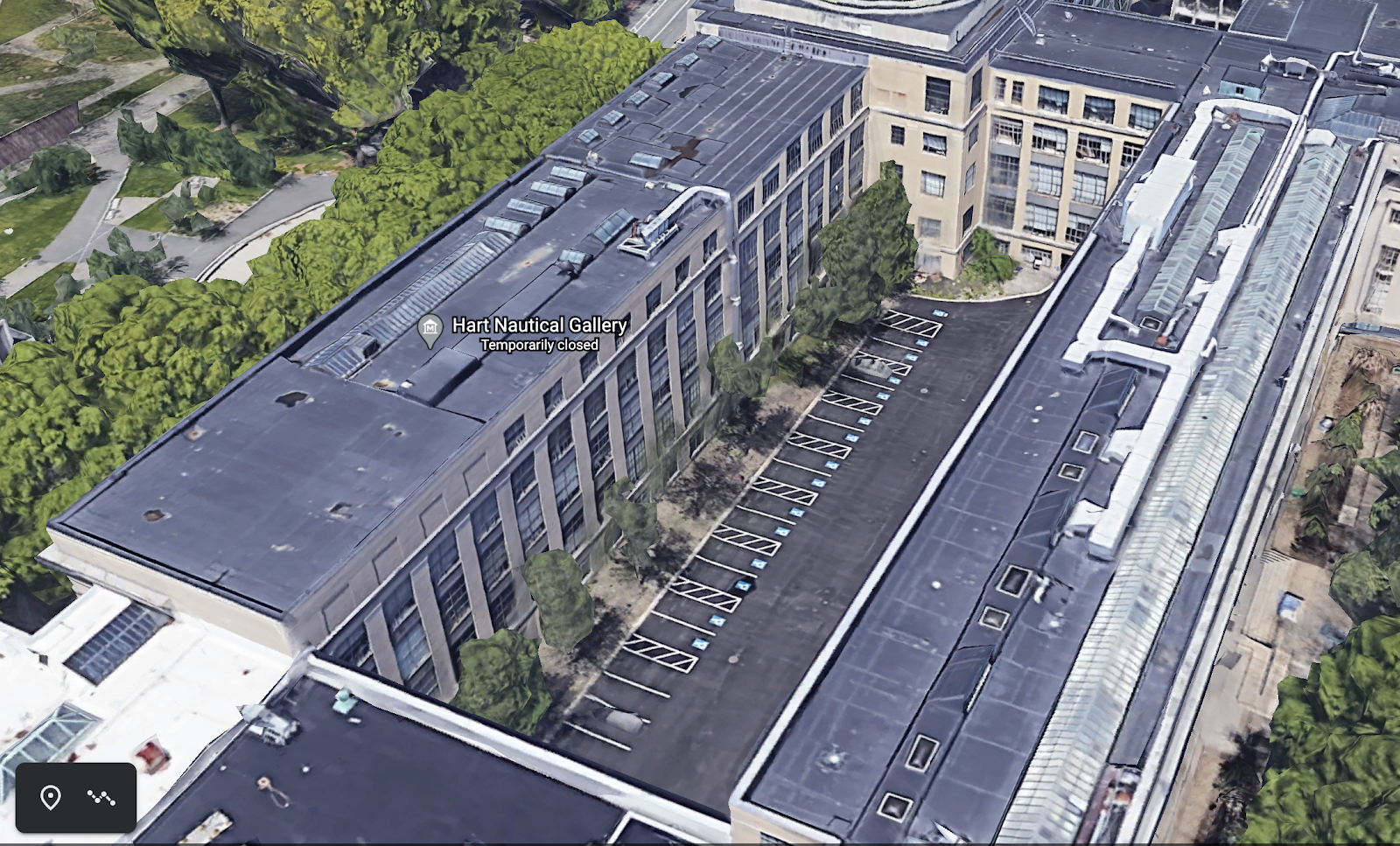
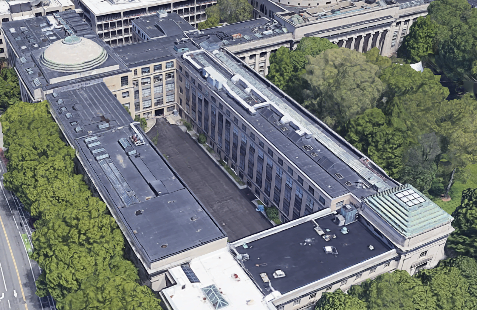
My group and I were tasked with designing a roof to cover the parking lot adjacent to Building 1 on MIT's campus. The space is entirely enclosed by four existing MIT buildings, with structural columns spaced 15 ft spanning the area's length. The space's footprint has an approximate length of 270 ft and a width of 90 ft, with a notch of approximately 20 ft by 60 ft in the back corner. Three of the four surrounding buildings have a height of roughly 70 ft, while the fourth is slightly lower, though the exact height could not determine given the supplied documentation.
We were given the freedom to work with any material we desired. However, we were also given three constraints to take into account when designing our roof. One, the roof had to sufficiently provide cover against the elements: snow and rain, specifically. Two, the roof needed to be naturally ventilated. Three, the roof needed to allow for the natural light to continue to flow into the space.
Precedents & Inspiration
My team and I had two concepts we wanted to use as inspiration for our roof. The first was the idea of intricate shells, and one design in specific: Eladio Dieste’s Gimnasio Y Colegio Don Bosco in Uruguay. We liked this design for its elegant undulating shape and for the sawtooth window structure, which allowed for more refined control of entering sunlight. The second concept was open timber structures, first inspired by simple pergolas, then evolving as we researched more complex timber structures. We were inspired by the warm, and natural feeling timber evokes in space and how sustainable it is compared to other typical building materials. Using wood would also allow us to source material very locally from one of New England’s many forests. Drawing inspiration from projects such as Centre Pompidou-Metz by Shigeru Ban, we ultimately decided to combine these two concepts and devote our semester to creating a timber grid shell roof.
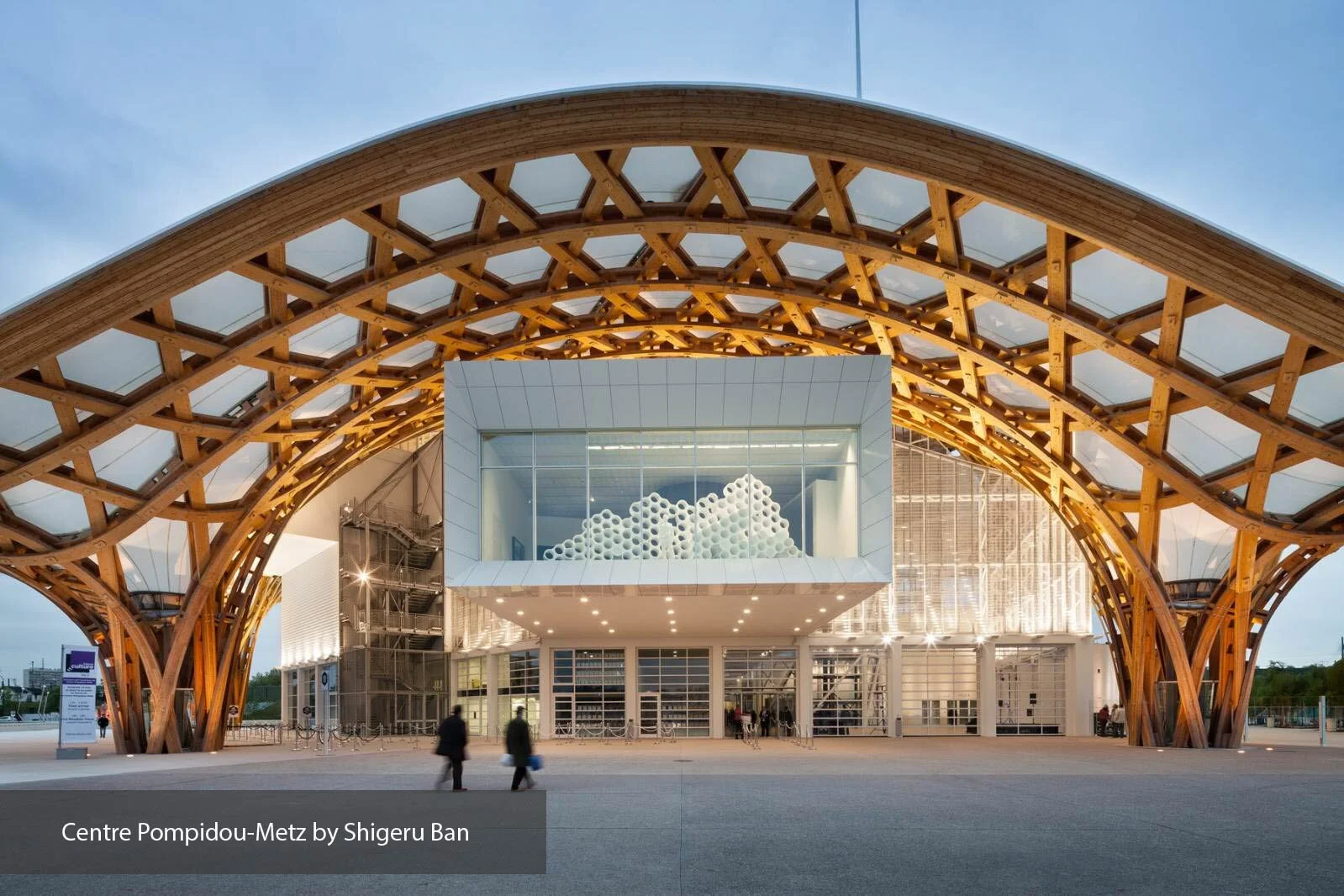
PHOTOS BY DIDIER BOY DE LA TOUR, JAMES EWING
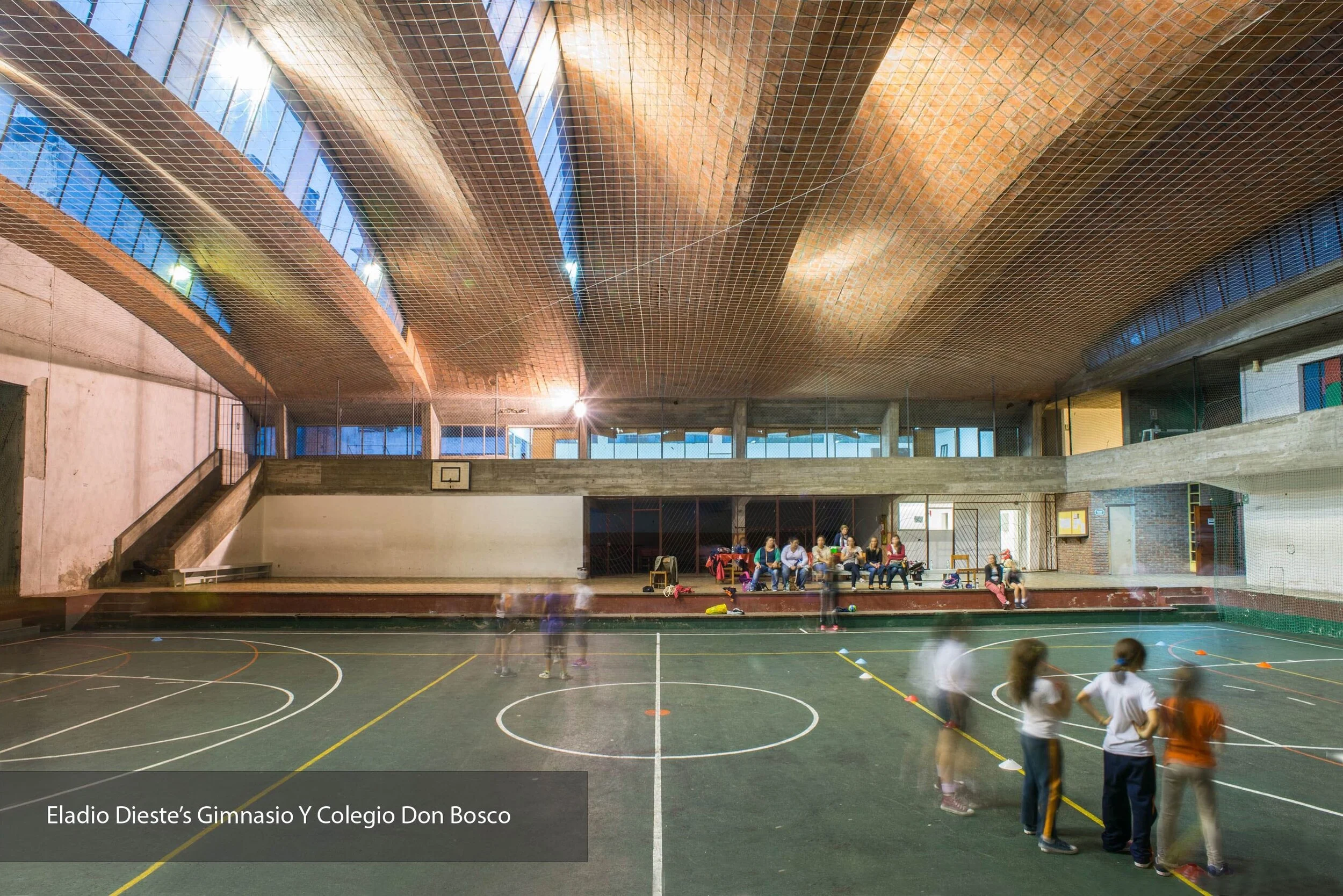
PHOTOS BY LAURO ROCHA
Designing The Dryad
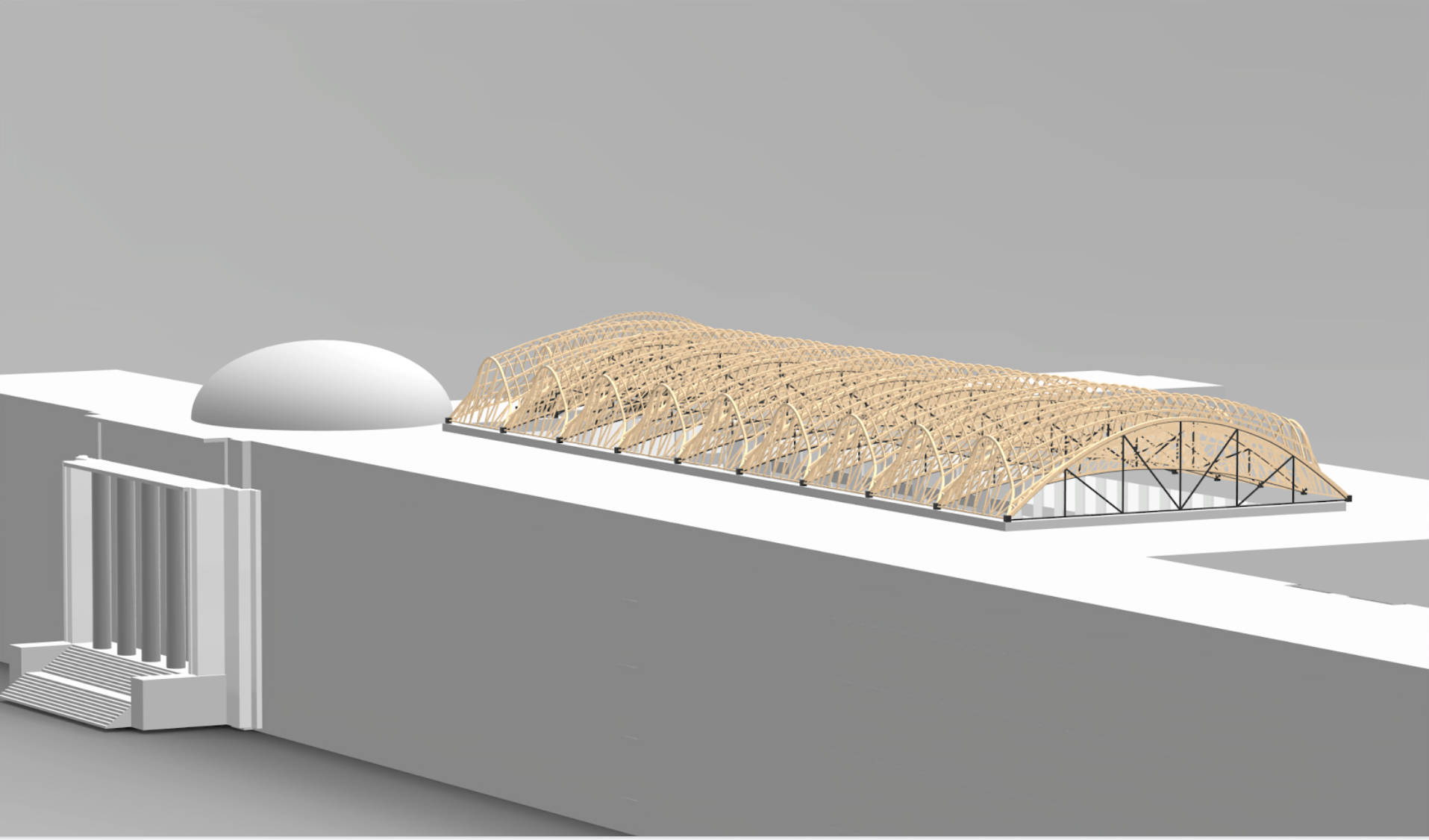
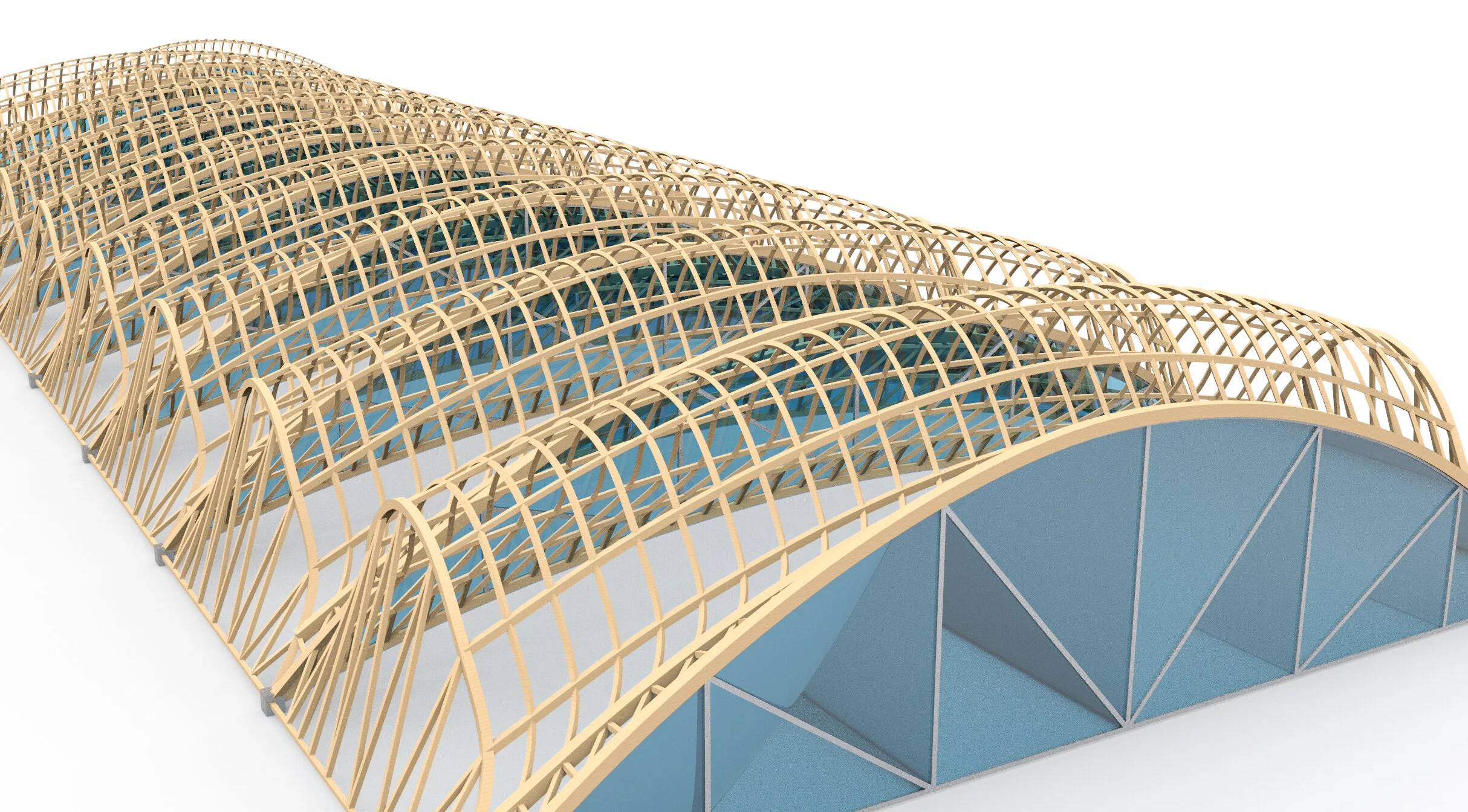
Combining our inspirations into one structure, we came up with The Dryad. The Dryad is a modular timber gridshell with a shape inspired by Dieste’s Gimnasio roof. The primary structural material is locally sourced white oak, chosen for its nativity to the New England area and for its light color to complement the white of the surrounding buildings. To keep the structure lightweight and to allow for light to filter through, the structure will be covered in translucent ETFE paneling.
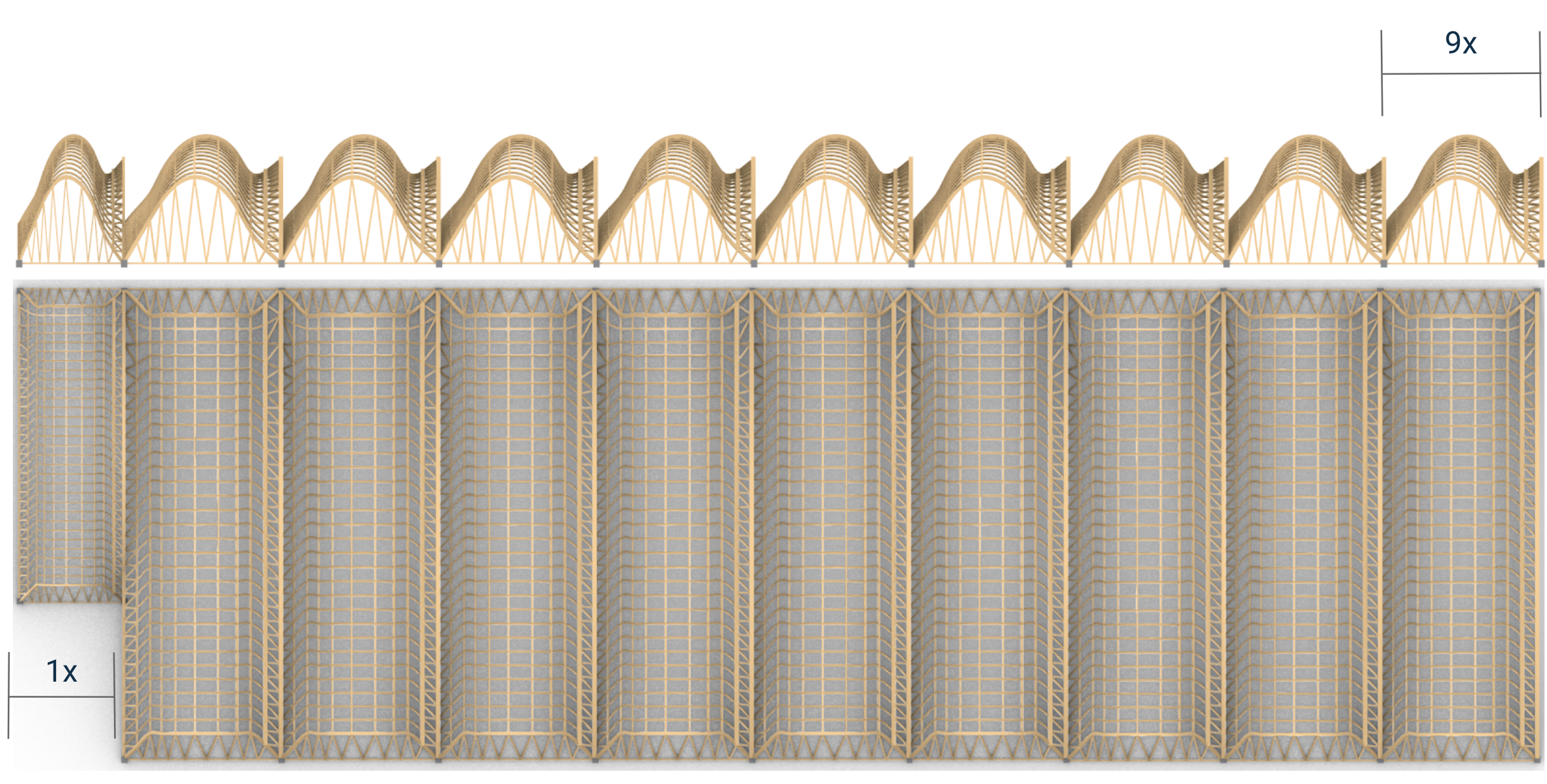
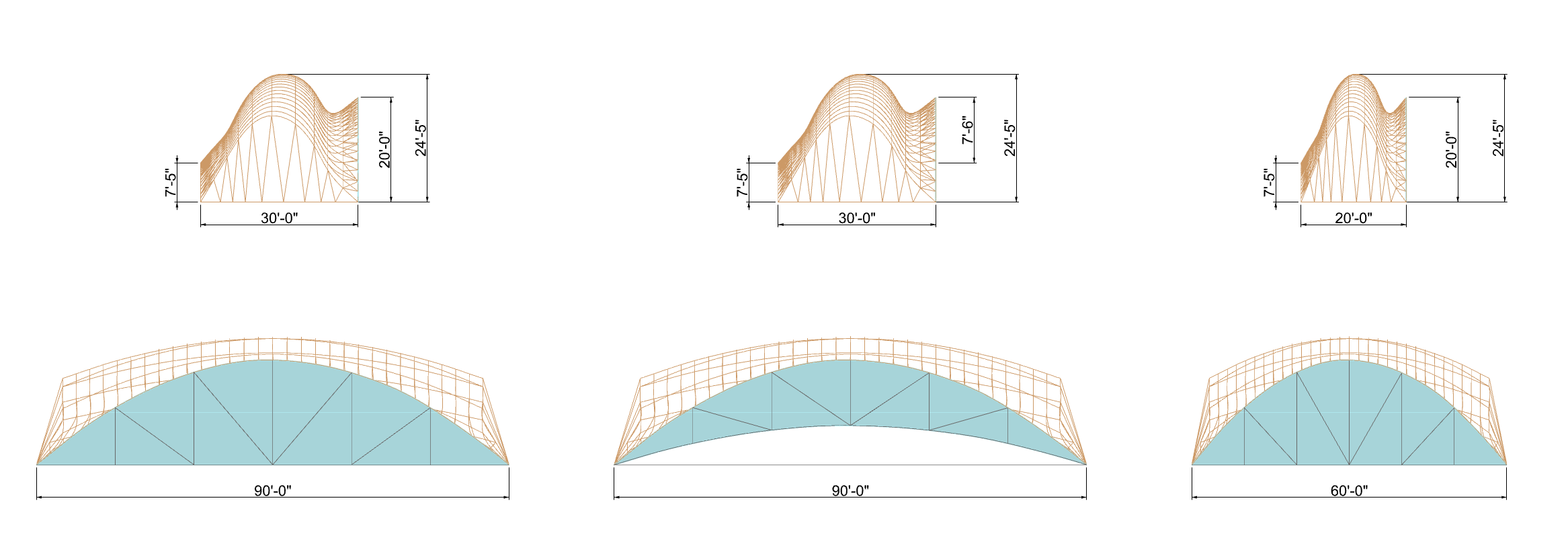
The overall design of the gridshell comprises nine self-supported modules spanning the length of the roof, each module 30 ft in length and 90 ft in width. The last, tenth, module is smaller, at 20 feet by 60 feet, to consider the back notch. We selected the sizes to line up with the existing structural columns of the surrounding buildings, which are spaced at every 15 ft. Finally, a glass windowpane fronts each module to allow for direct sunlight.
Renders: Nebyu
Dryad Breakdown: The Gridshell
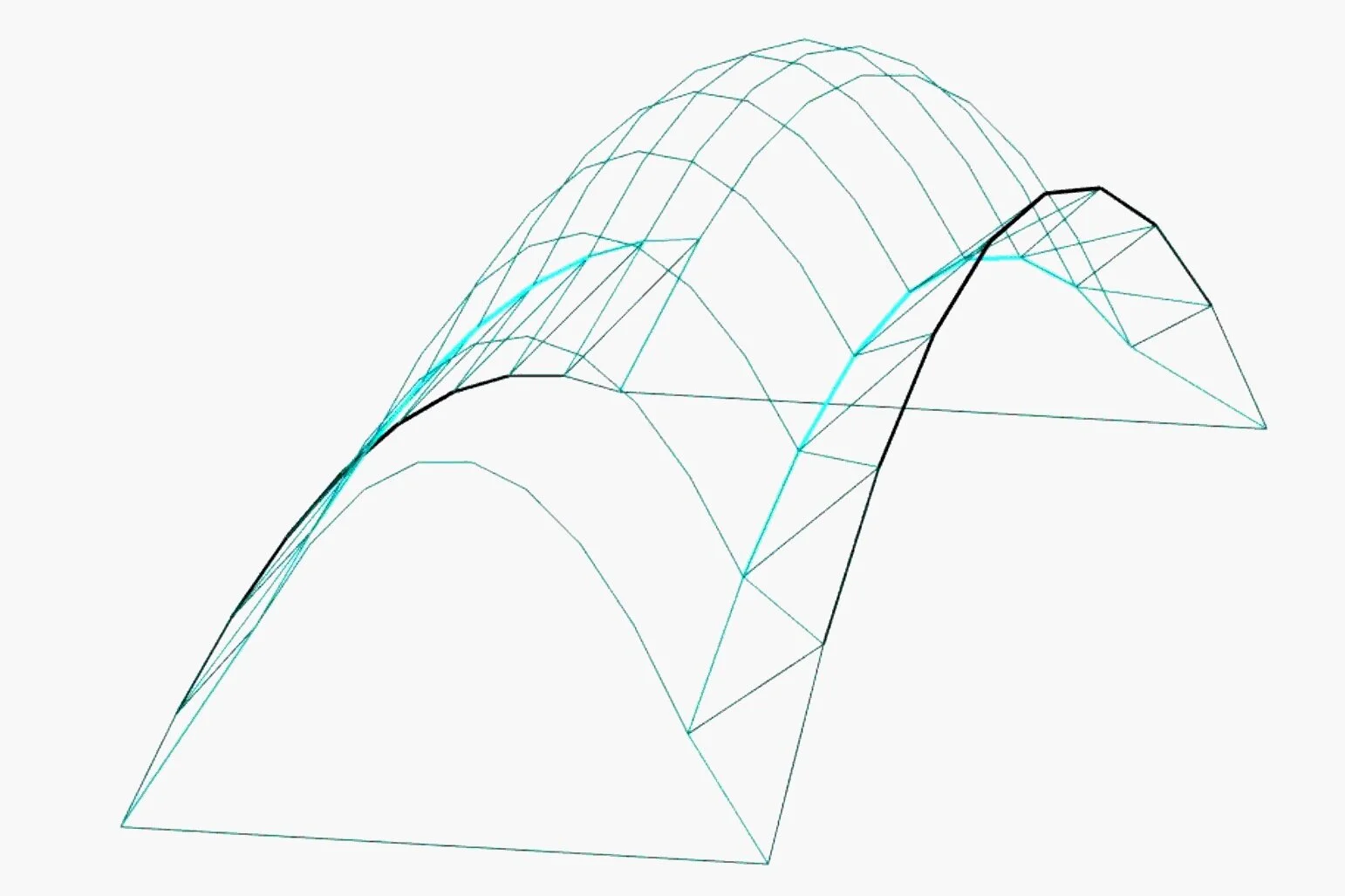
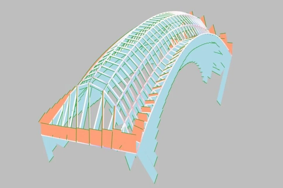
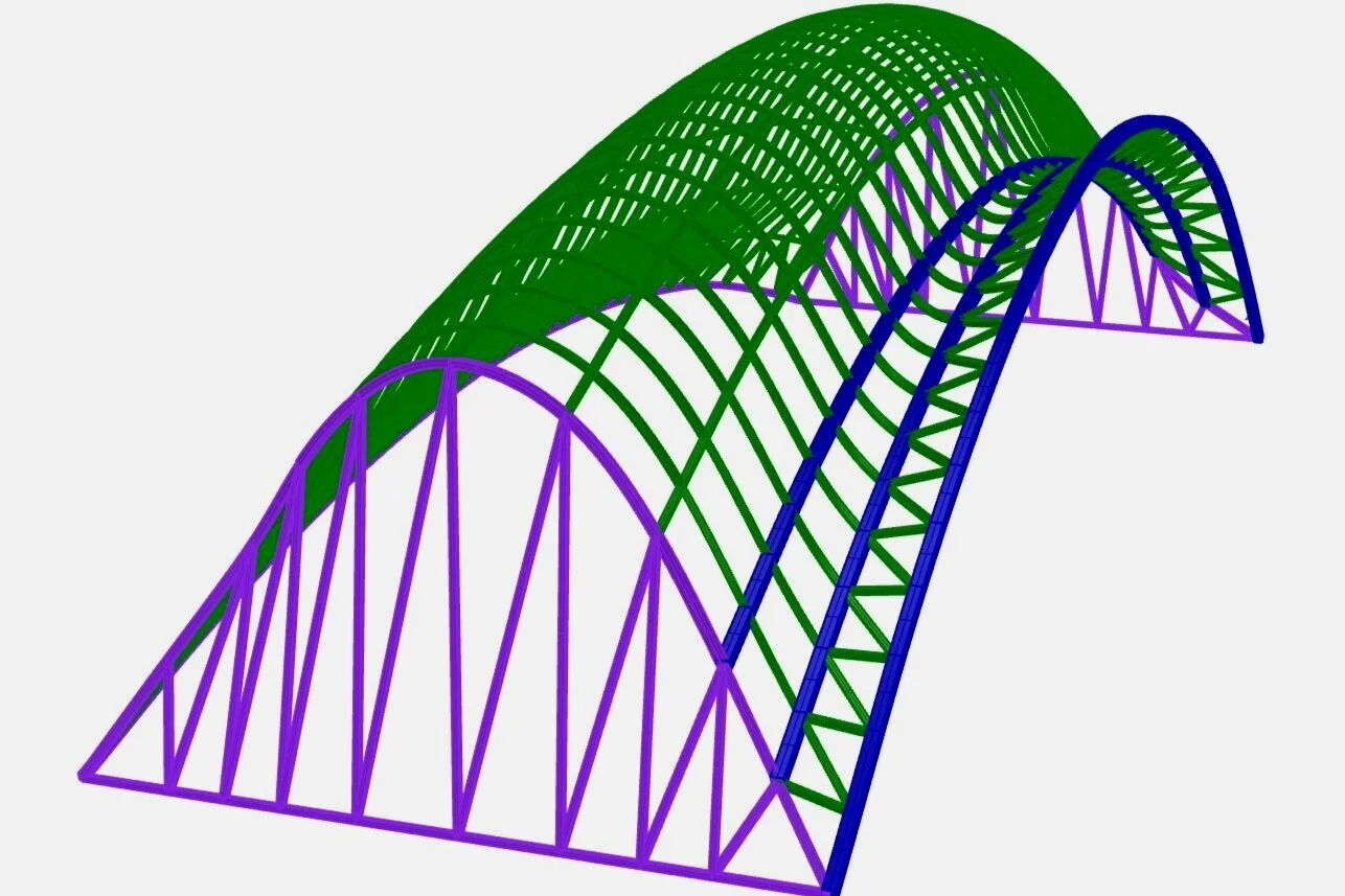
The primary structural system of our roof is a gridshell. We specifically selected this system for three reasons: one, the double curvature of the gridshell provides vertical and lateral resistance, providing stiffness and strength to the structure. Two, gridshells are typically very lightweight since they are composed of many small, interlocking members, so we know that it is likely possible to support the roof on the existing MIT buildings. Three, gridshells are commonly made using timber, which we wanted to use for its sustainability and warmth.
At first glance the odd shape of the gridshell is puzzling, however, this unique shape comes from the fact that the shell was designed using a force density technique. Meaning that we let resulting the forces in structure determine the structural form for the structure. This method of form finding was picked for the shell because it would ensure the minimum amount of stress in the members resulting in smaller corrections, and in effect less timber and less weight. The force density + form finding was accomplished using a series of MATLAB code. Once the overall shape was found additional members were added to get a visual pleasing and manageable grid spacing
Force Density (MATLAB): Claire + Densifying Grid: Nebyu
Dryad Breakdown: The Modules
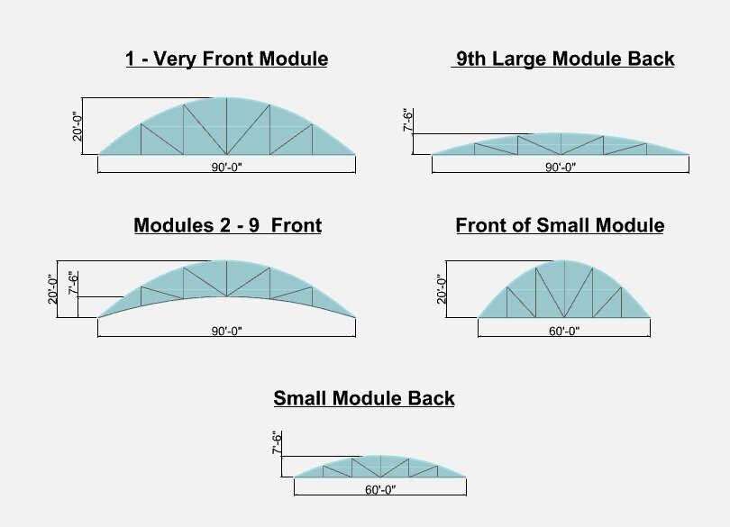
The Dryad consists of 8 identical modules and two edge cases at the very front and back of the structure. The standard module is 30 feet in length and 90 feet in width, whereas the smaller back module is 20 feet by 60 feet. The front arch of each module reaches a height of 20 feet, the back arch reaches a height of 7 feet 6 inches, and the tallest point stands at 24 feet and 5 inches.The front of each module has glass paneling and a steel truss system to support the structure.
Each Module in the 10 module system is considered to be independent of one another. This was done deliberately as a redundancy incase of failure and to make the construction process simpler. The details of how this independence is accomplished is described in the final paper under section “Structural Assumptions”
Renders: Nebyu

Dryad Breakdown: Member Sizing
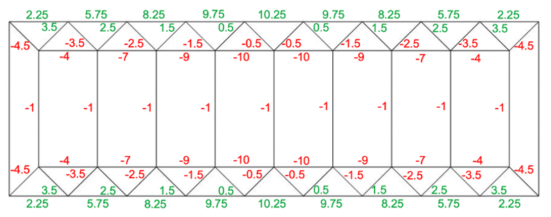
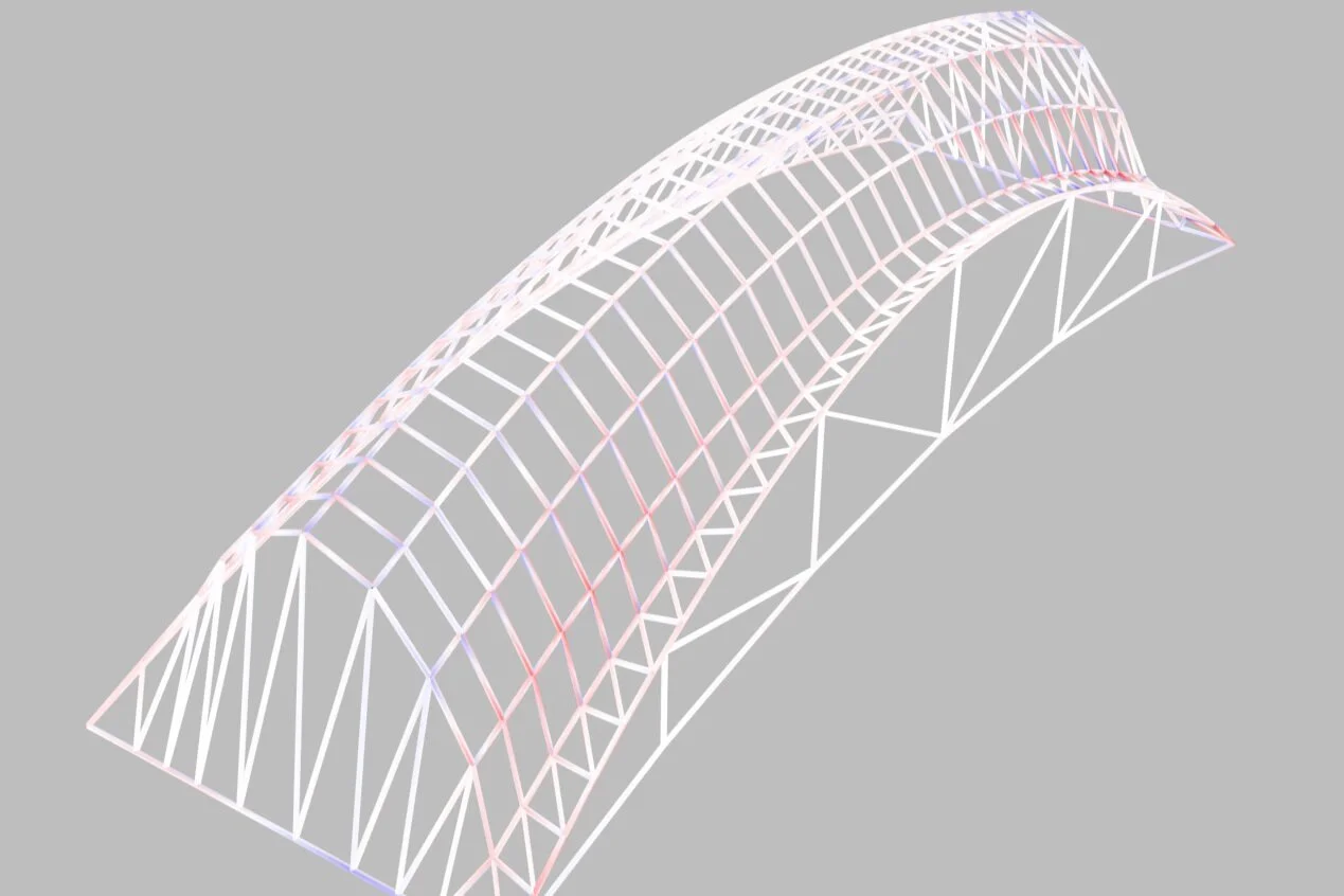
To calculate the members' forces, we relied upon Karamba because the gridshell has 750 members, so doing a hand calculation did not make sense. In Karamba, the structure was supported at the four corners, with three out of the four being pin connections and one corner being fixed to prevent rotations. The structure was then loaded uniformly with a 17.5 pound/inch squared dead load and asymmetrically (half load on the front half of frame) with a 30 pound/inch squared live load.
Upon analysis, there were three main hierarchies of forces, with the highest forces in the three arches making up the front of the gridshell. The second highest forces in the side webs plus the side and back edge beams, and finally the lowest forces distributed in the members making up the body of the gridshell. We verified the model's accuracy in the fact that the vertical and thrust forces matched up with expected values; furthermore, regions of tension and compression matched up with those of the force density model.
Based on the forces and the strength of our wood of choice, White Oak, to be 2 KSI, we picked three section sizes: 6"x 6" for the three front arches, 4" x 4" for the side webs and side/rear edge beams, and finally 3" x 3" for the body members.
One thing to note about our member sizes is that we decided to build our cross-sections up from 2 separate members. We made this decision because, in curved timber gridshells, it is much easier to get the curvature to work when layered sections are chosen. Furthermore, building up the cross-sections acts as a safety factor in case one-layer breaks, and lastly, it makes getting the gridshell to shape easier during construction
Member Analysis/Sizing: Nebyu + Karamba Setup: Claire
Dryad Breakdown: Lighting Study
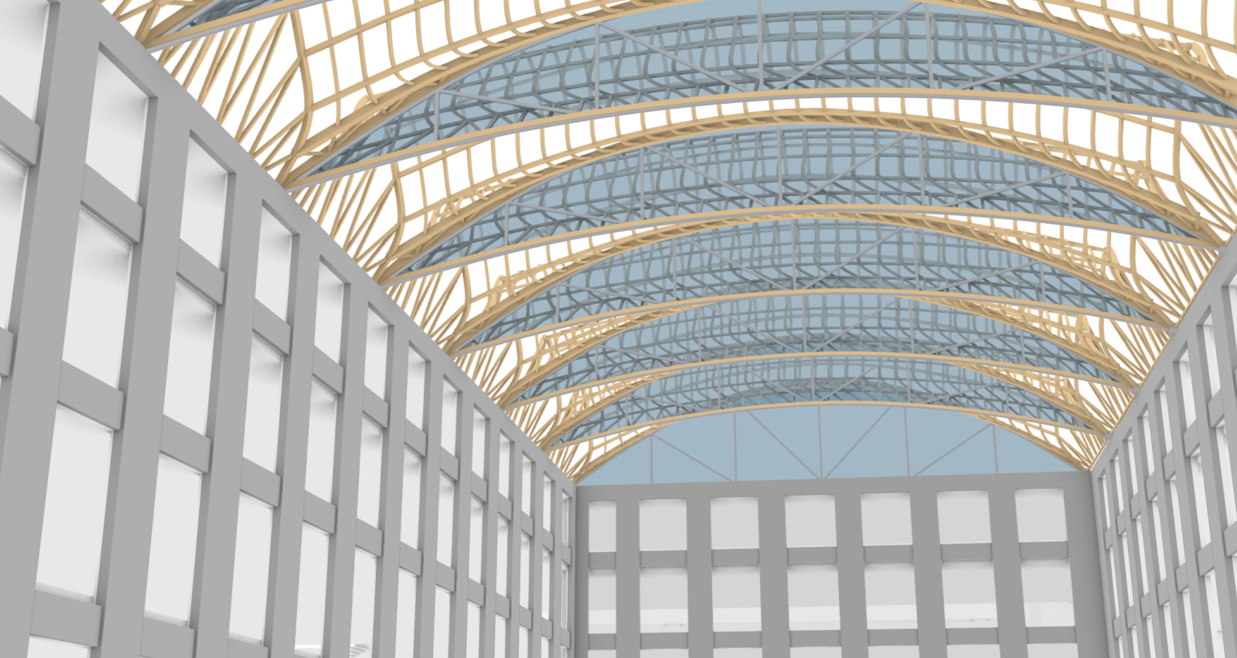
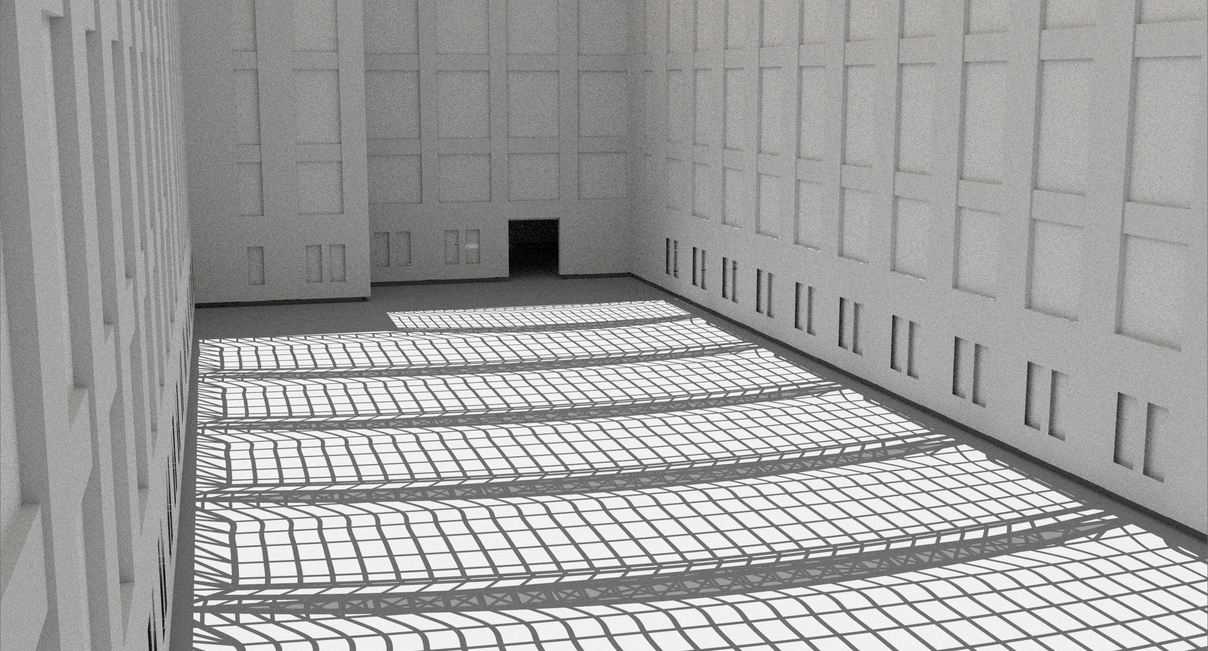
The lighting of the existing space was a major driving factor in designing the roof. There were two primary components: first, the indirect sunlight coming in from directly above, mostly diffused by our wooden members and the ETFE paneling; second, the direct sunlight coming through the glass windows. The gridshell, coupled with the ETFE paneling, allows for patterned light to be diffused into the space, giving a lively, unique view to all the people who stand within it.
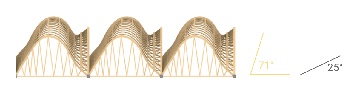
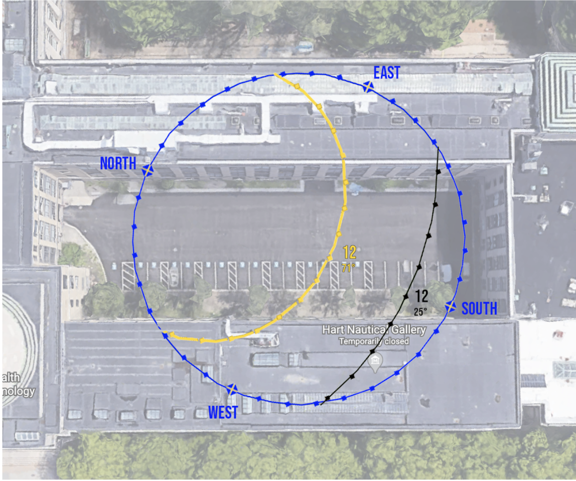
To design with the direct sunlight in mind, we studied sun patterns in the area, determining the placement and the angle of the sun at this specific location. To get an accurate picture of the sun using just two points of the year, we focused on the Summer and Winter Solstices. We determined that the highest angle of the sun would be 71 degrees in the summer versus just 25 degrees in the winter.
Once again, inspired by Dieste's Gimnasio, the sawtooth design is meant to allow for some control of the sunlight entering the space. The modules run from left to right, shown below, so that the glass panels face the southeast. In the summer, the direct sunlight is partially obscured by design due to the high angle, limiting the space's summer heat. In contrast, the low angle in the winter allows for sunlight to flow smoothly through the room, allowing for more warmth.
Lighting Study: Sabrina
Dryad Breakdown: Roof Supports
Based on Karamba analysis we determined that the vertical force at the front support was 42 kips after calculating our reaction forces, while the horizontal forces were 52 kips. The vertical force is 23 kips at the back supports, while the horizontal force is 34 kips. To account for our double-layered construction, we had to design the support to connect two members for each line in the grid.
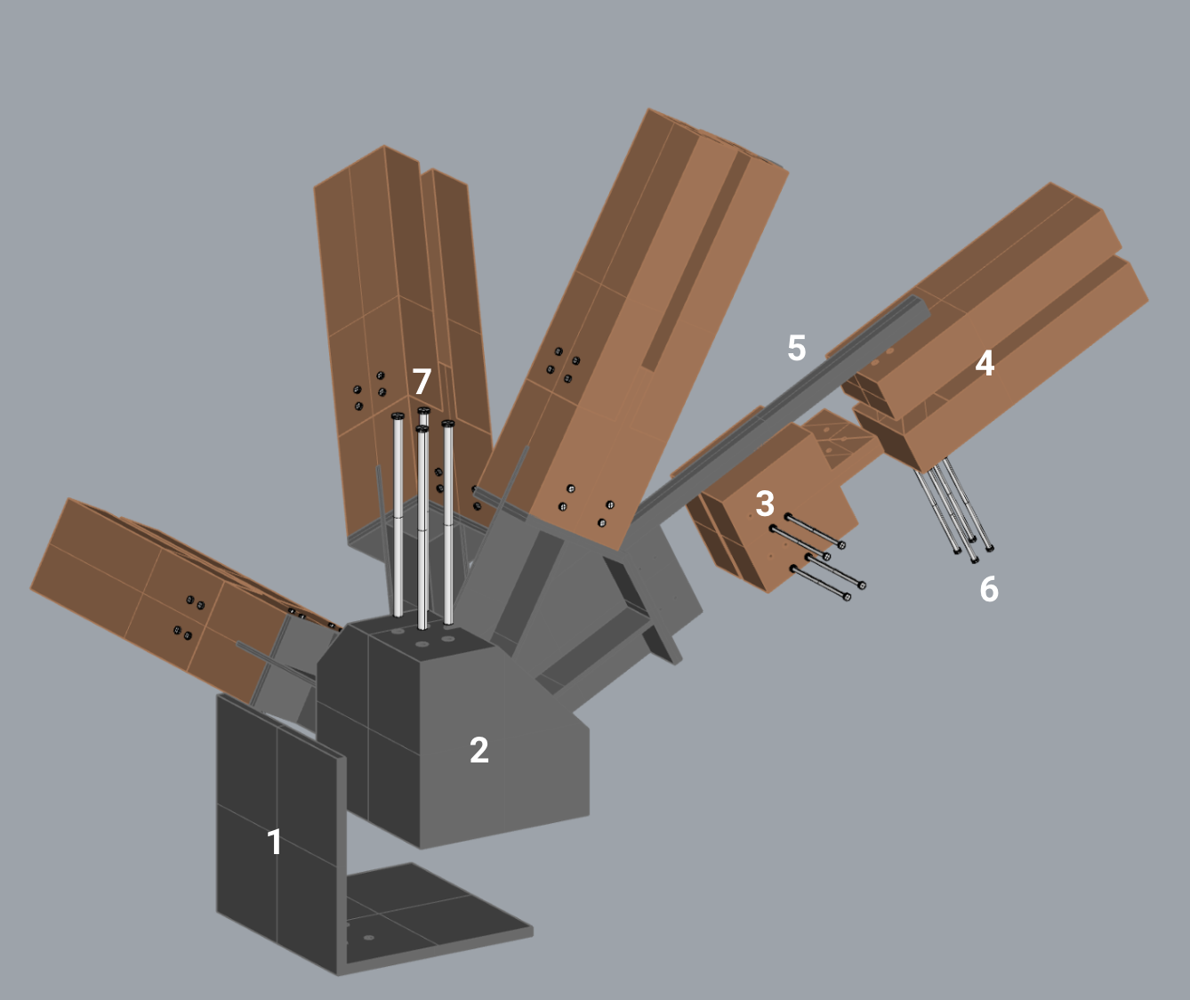
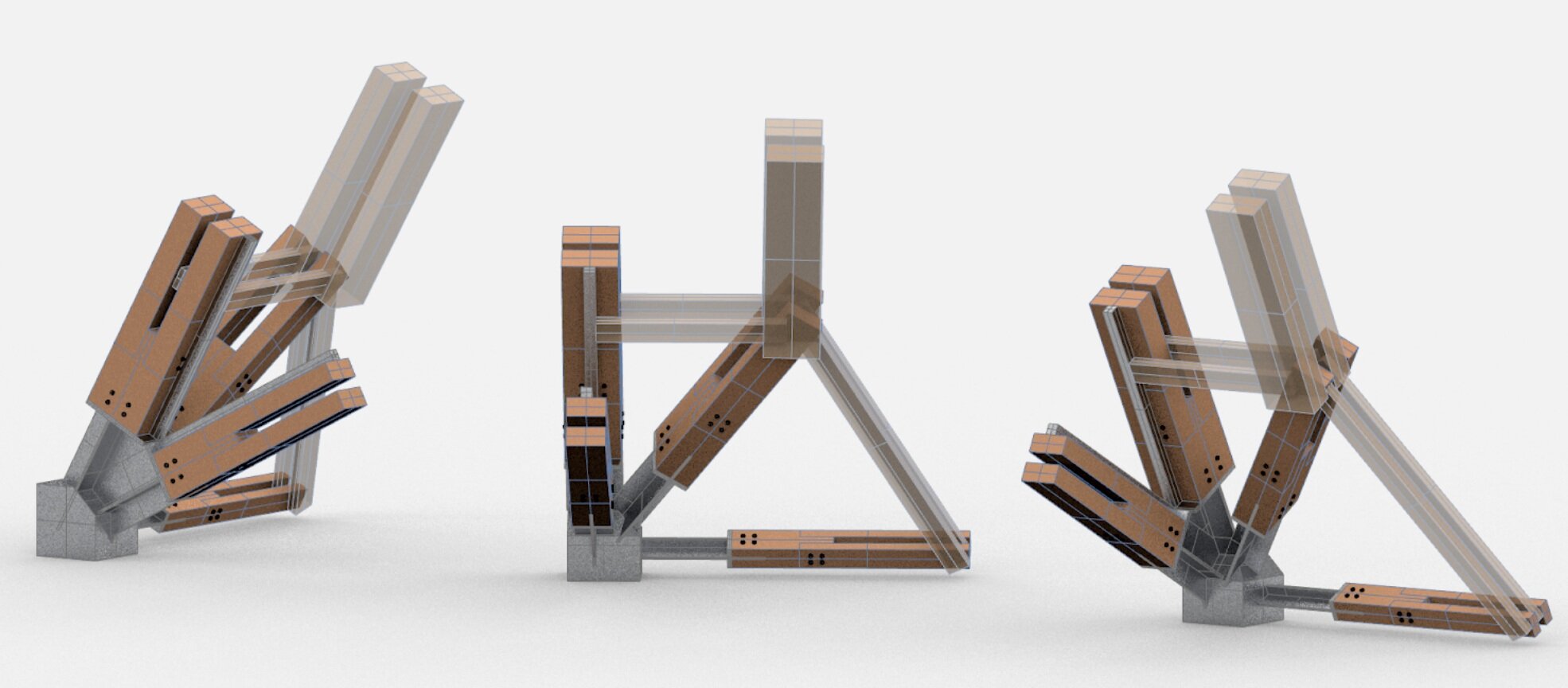
The support is composed of seven parts, as labeled in the upper right image below. In order, each component: 1) A steel L channel, bolted to the roof, 2) the steel base, bolted to the channel, 3) our custom wood piece, bolted to the gusset plate on the steel base. This piece allows for our split timber members to connect back to the base in a single support with a simple shear connection. Next, there is 4) our wooden members, 5) the steel window trussing, welded to the support, which holds our window and acts as a steel tie, 6) ½ inch diameter bolts and 7) 1 inch diameter bolts.
To account for variability in the gridshell members and angles, we developed a Grasshopper script and parameterized our support. With this, we could perfectly match each support to the beam sizes at each specific corner. The dimensions of the base were also parameterized to allow flexibility in the design. The editable parameters are beam offset, gusset thickness, gusset length, base size, channel size, beam sizes, the spacing in between, the angles of the members, and the rotations.
Roof Supports (Renders & Grasshopper Script): Sabrina
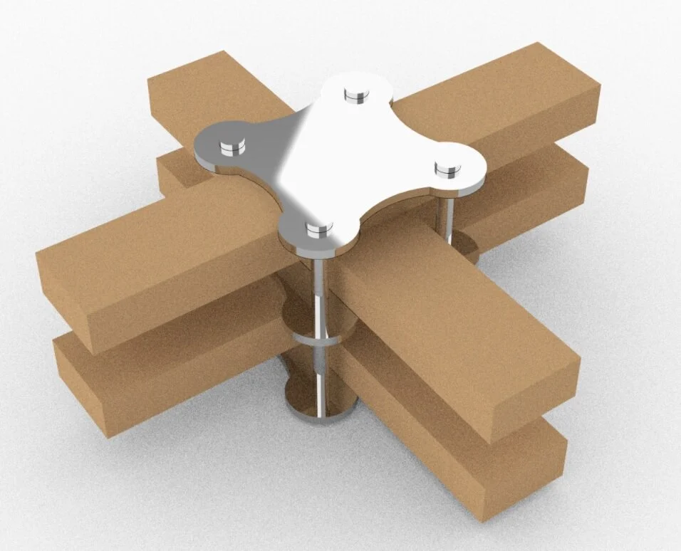
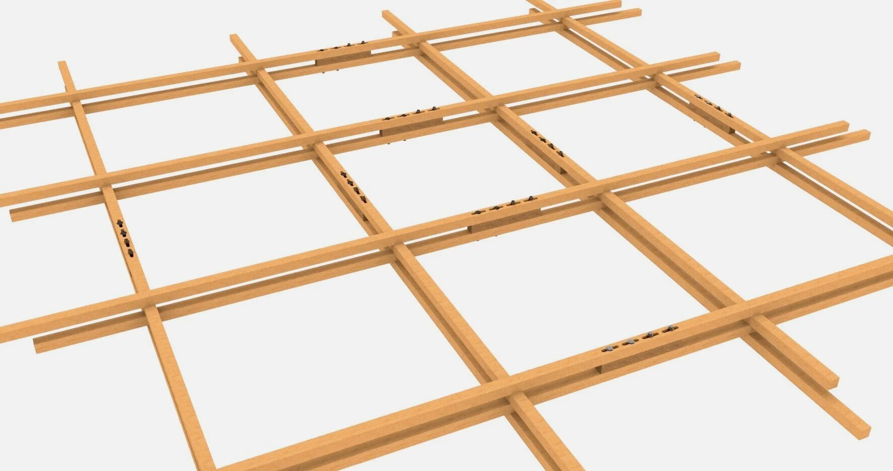
Dryad Breakdown: Grid Connections
As a result of the two-layer member structure described earlier, one of the most critical aspects of the proposed gridshell was the connection details between members. For this project, we looked to implement a modern-day version of Frei Otto's sliding bolt used on the Mannheim gridshell. This connection detail dubbed the "plate connection," involves running each grid member through a series of steel plates that can then be tightened to secure the timber members.
The benefits of such a connection are that it allows the timber members to slide relative to one another, and this is crucial to achieving the curvature of the grid using linear boards. Furthermore, this connection detail makes construction easier, by allowing the gridshell to come to shape by simply lifting it into place. A secondary connection detail for our gridshell is where the grid goes from square to triangular. For these areas, we proposed a connection detail involving Y shaped steel plates that would slide into the timber members and be bolted tight as depicted below.
Plate Connection: Sabrina + Triangle Connection: Nebyu
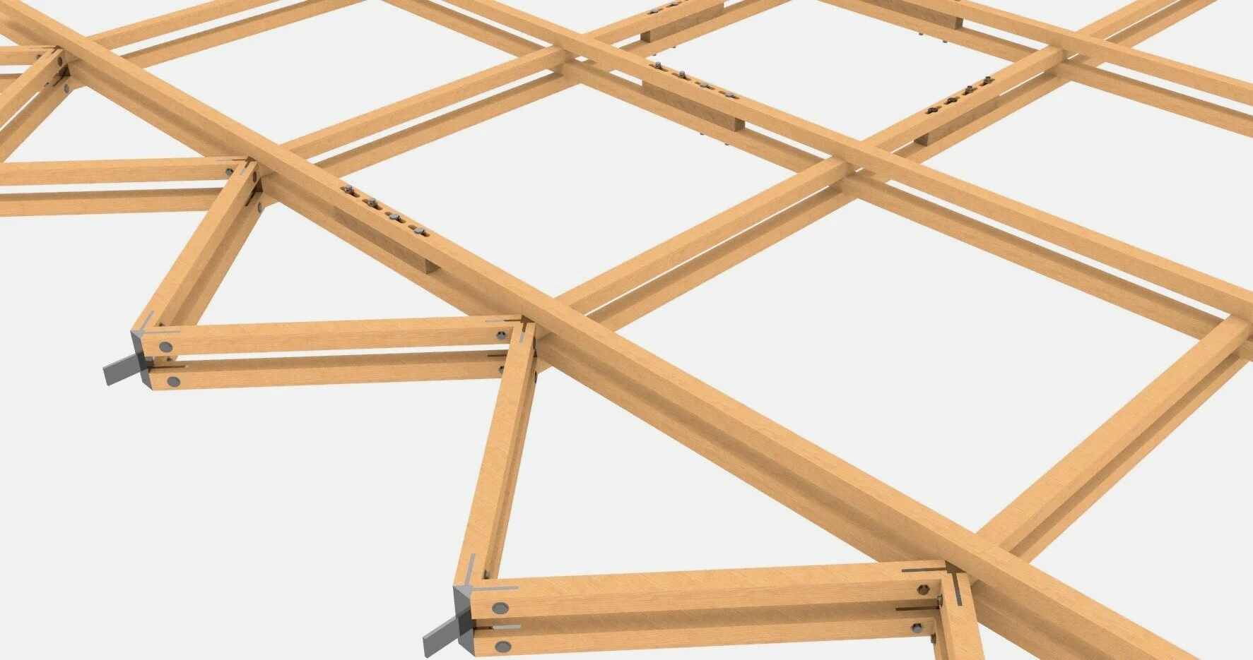
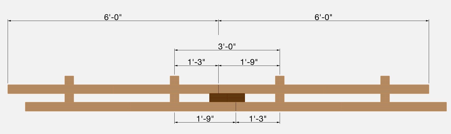
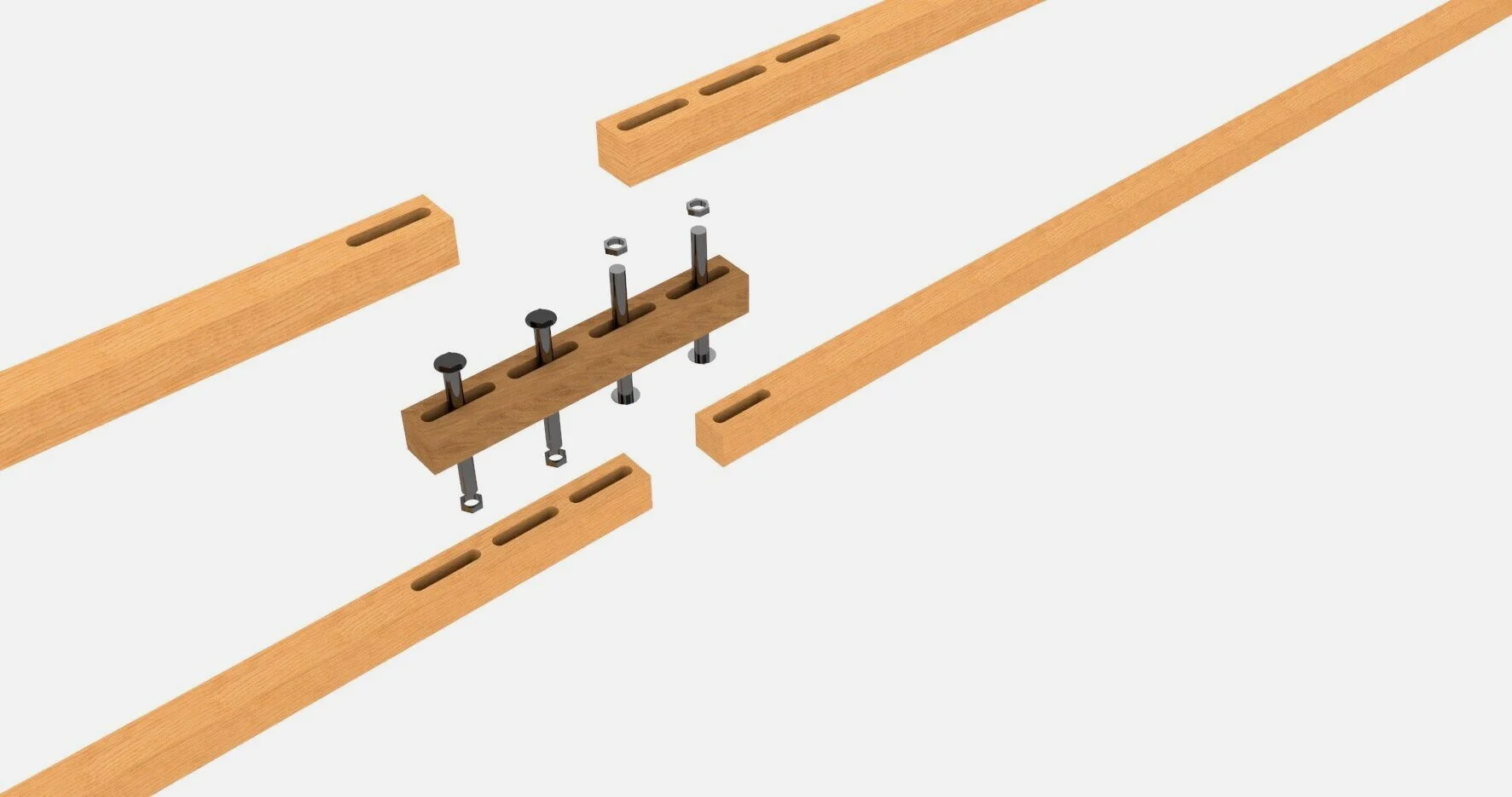
Dryad Breakdown: Splicing Detail
Understanding that the one continuous piece of timber could not span the 90 feet, one area we focused on was the timber's splicing details. Although the timber for the gridshell in actuality is curved and more complex, we idealized the splicing detail for a non-curved section for the sake of simplicity and proof of concept. The images below show what a possible splicing detail could look like for a 3 foot by 3 foot grid using 6 foot long members. The figures below also shows what the actual curved gridshell section might look like. In the images below, the darker rectangle represents a shear block, this block not only helps transfer shear between the layers of the grid, but it also acts as a way of connecting the two layers at the splice. The figures also show a proposed connection detail for the splice.
Splicing Detail: Nebyu
Dryad Breakdown: Window Paneling
For the window paneling/truss, one crucial thing to note is that for all the window trusses, the top chord of the truss is an edge beam of the arch and that the bottom chords of the truss are what acts as the tie of the gridshell so that no thrust is put on the existing structure. Upon analysis using Karamba, we realized that the vertical webs of the truss are zero force members. As a result, the only thing necessary for the window truss is that the bottom chord could handle the shell's thrust and that the bottom chord plus the webs could handle the lateral force due to wind + snow loads.
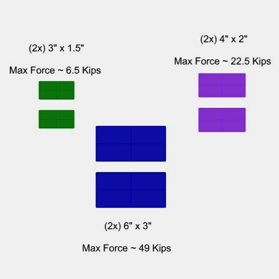
Calculating for a lateral load of 30 lb/sqft and that each triangular subsection of the widow distributes its lateral forces equally on the surrounding trussing, it was calculated the centermost vertical web receives the most lateral force at roughly 3 kips. Taking the average compressive strength of steel to be 22 KSI, we get that approximately 0.14 in2 of steel is needed; thus, a ½” by ½” section for the webs is adequate.
Based on the Karamba analysis, there is a net 86 Kips of unresolved thrust that the bottom chords of the window truss must carry.Taking the tensile strength of steel to be 30 KSI means the chords will need a cross sectional area of 2.87 inches squared. However, some edge cases only need to carry 52 kips (1.73 inches squared) or 34 kips (1.13 inches squared), Thus, for the chords carrying 86 Kips, a 2" x 2" section is picked, and for the chords carrying 34 kips and 52 kips, a 1.5" by 1.5" section is selected. The five types of window panels/trusses are shown in the images below.
Window Paneling: Nebyu
Dryad Breakdown: ETFE Roof Paneling
As we wanted the roof to be a weather barrier as well as allow light to enter the interior, we needed a transparent or semi-transparent covering for the timber gridshell. After considering both glass and EFTE as materials, we decided on ETFE panels, as they are significantly lighter than glass, and can vary in transparency to create various lighting effects. The panels will be connected to the timber structure with clamps that are spaced across the grid. The total effect of the weight and embodied carbon of the paneling will be detailed in Section VI Weight and Embodied Carbon
ETFE Roof Paneling: Claire
Maxwell Load Path
A topic my team and I were asked to focus on in detail this semester was Maxwell Load Path, which is a metric of efficiency of a structural system measured in “Force•Length”. For the Maxwell Load Path of the gridshells we used the forces in each member captured by Karamba and multiplied it by the length of each member using a simple grasshopper script. The total load pat for all 10 modules of The Dryad, which includes the timber gridshells plus the steel window frames was 215,632 Kip•ft.
While difficult to gauge how efficient The Dryad is just based of this number; for reference, it was the smallest (which is better) by a significant amount in comparison to the other 3 groups. The other groups had roofs made of steel, concrete, and glass. This showed that the use of timber and ETFE made a significant impact on keeping self weight and forces/stresses down.
Maxwell Load Path: Nebyu
Weight
+
Embodied Carbon
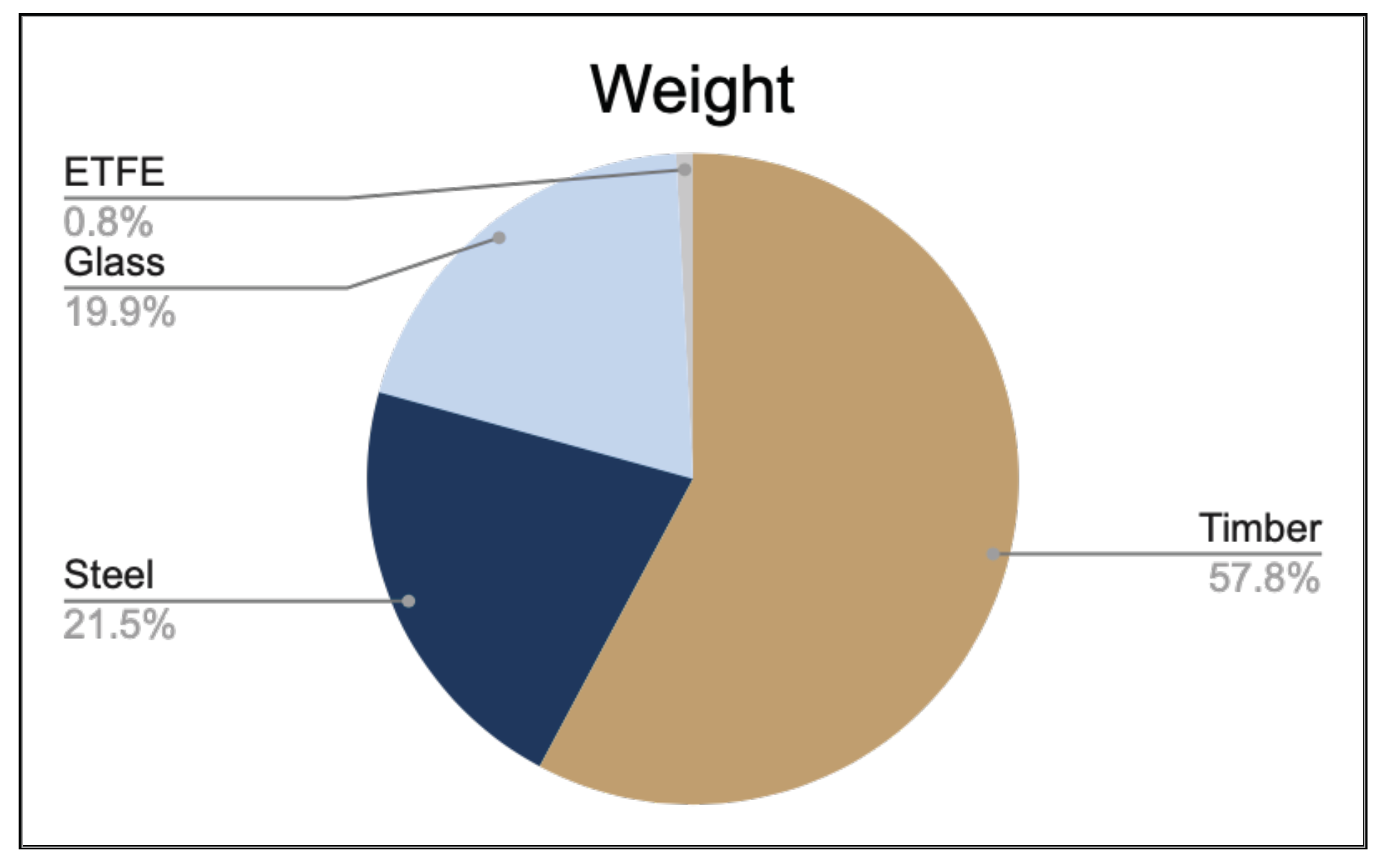
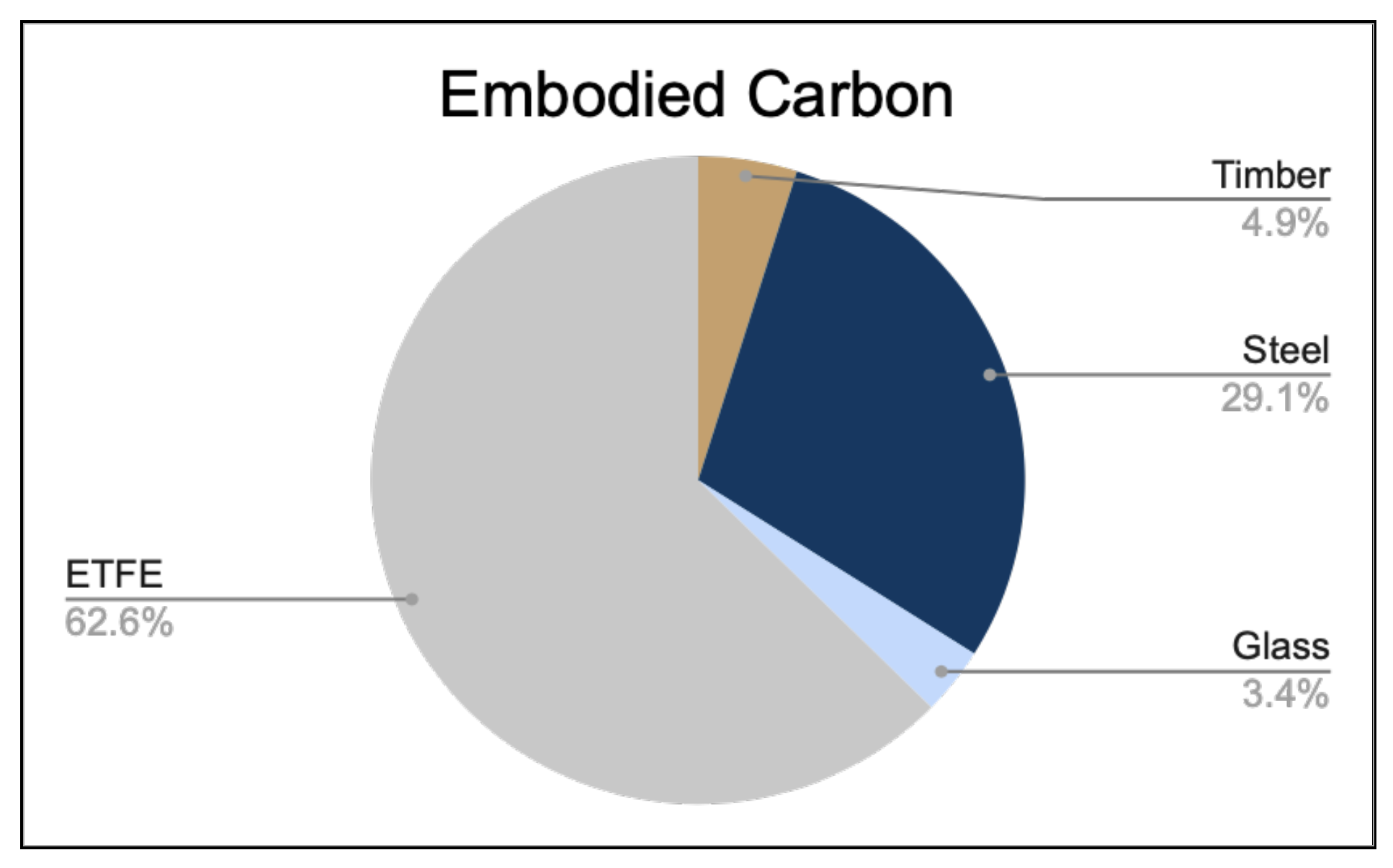
The two most significant categories that the roofs were judged on were their weights and their embodied carbon. This was the driving force in the development of The Dryad as timber gridshell to keep the weight and embodied carbon down. Upon analysis it was found that the weight of The Dryad was 8.52 lbs/sqft and the embodied carbon was 10.07 lbs/sqft.
Yet again, these values were the smallest of all four groups by a significant amount, showing that the use of timber and ETFE made a significant impact on keeping self weight and forces/stresses down. While the ETFE did drive the embodied carbon higher than anticipated it seems that it was worth it as glass would have increased the weight of the roof multiple times over.
Weight Embodied Carbon: Claire & Nebyu
Final Product
+
Future Investigations
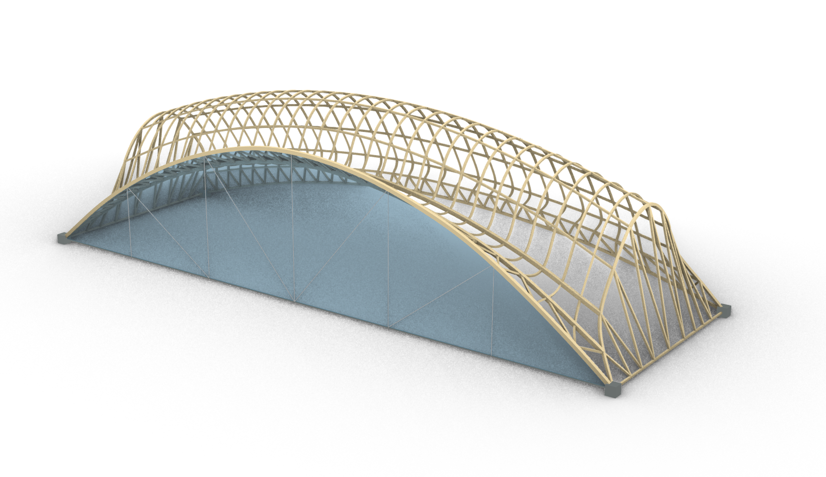
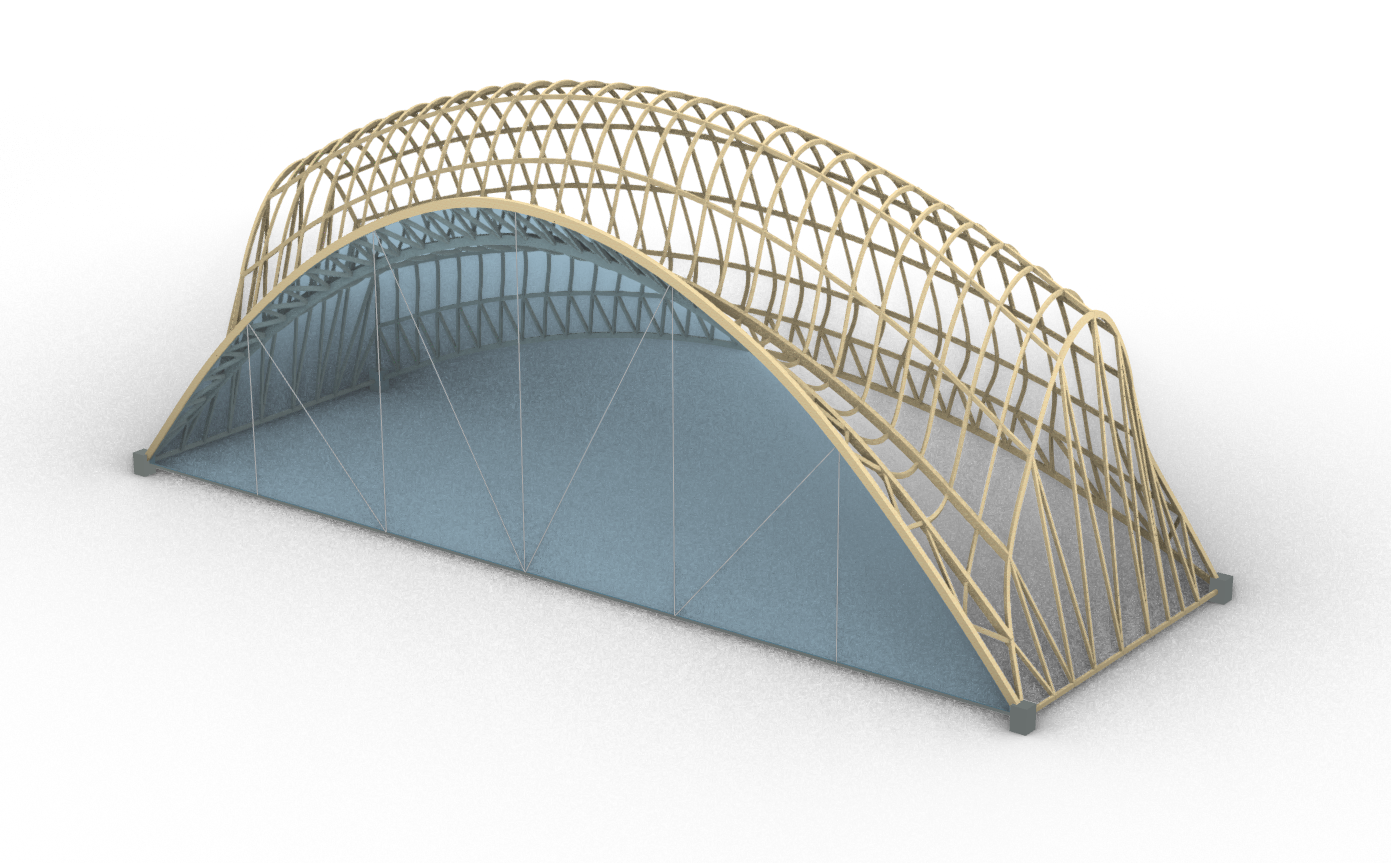
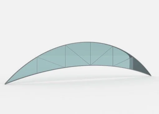
Below are renders of the final product from an exterior view and from an interior view.
Some areas that we did not have time to investigate in detail but would with more time are:
A feasibility study on the use of Glulam vs. Timber members for the gridshell. Looking at if the ease of construction of Glulam would be worth the additional embodied carbon.
Drainage study on how the water and snow of The Dryad can be rerouted to the existing drainage of the surrounding buildings.
Thermal study on how to maintain the temperature of the enclosed space if the space is to be used year round.
For all sections more detail can be found in the “Final Paper” linked at the top of this page. Additional Topics in the final paper include:
Structural Assumptions
Buckling Calculations
Detailed Construction Plan
Existing Building Weight Bearing Capacity Analysis
Uplift Calculation
Lateral Force Calculation
Embodied Energy + Weight Breakdown